Copyright 2024 - Capnetix, LLC

Wiring in the motor control board

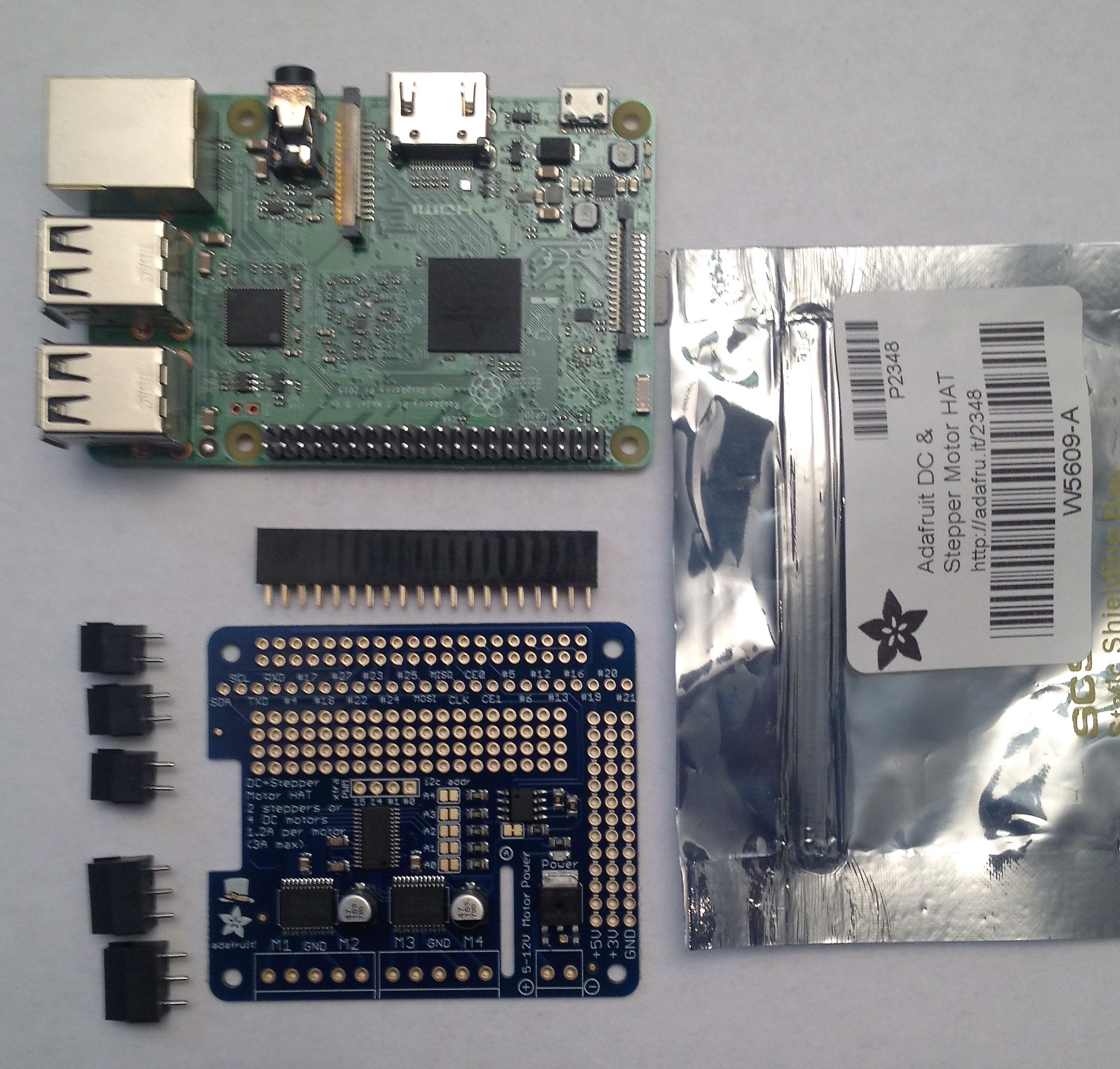
My MotorHAT came in the mail from Adafruit.  Always a happy moment when parts come in the mail.


First thing I did was open it up, and solder on the headers, just like it says in the docs. (That's a picture of their pretty soldering, not mine).

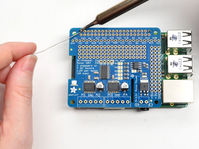
It's pretty easy to do, once you get the hang of it.


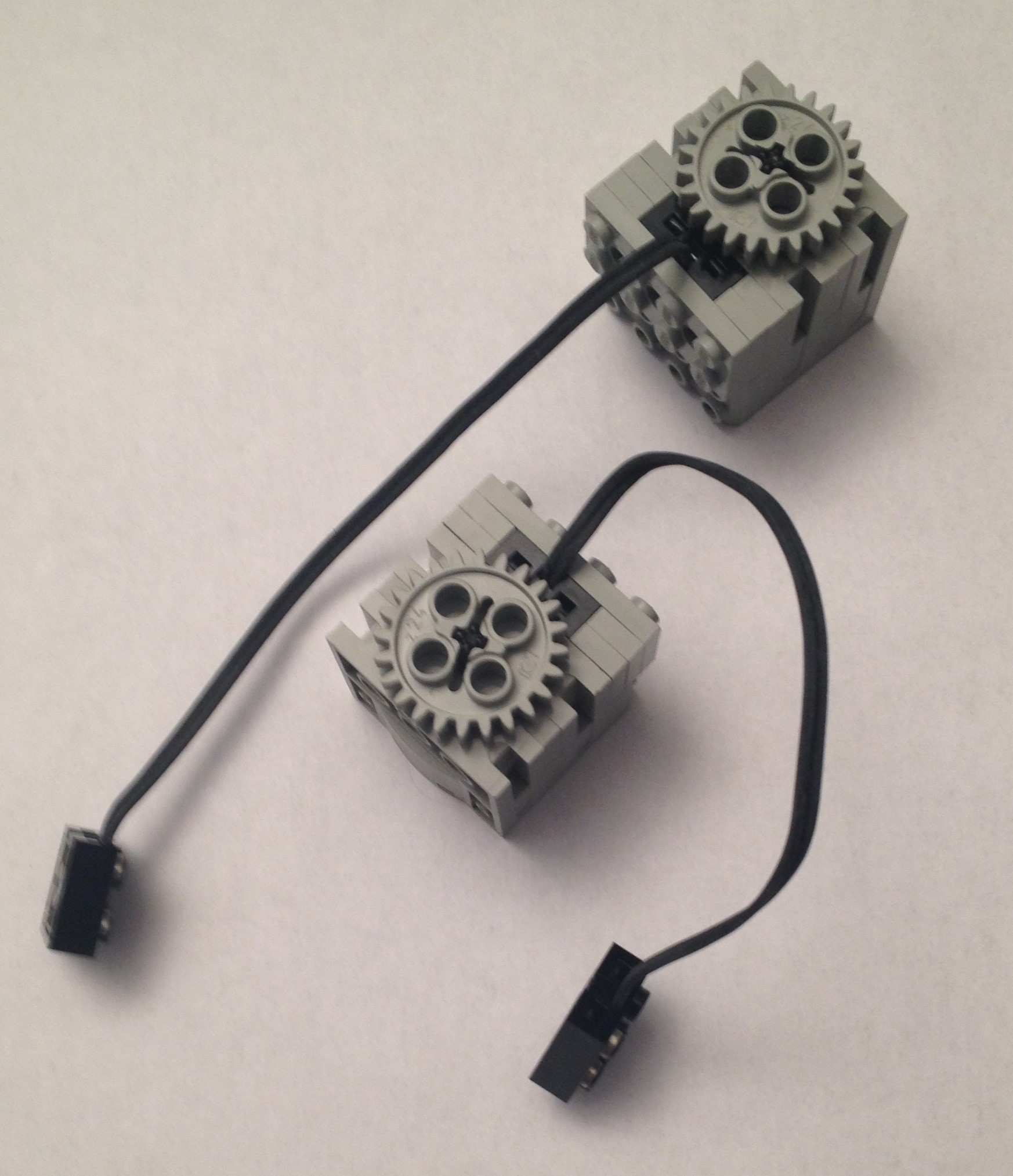
Once all the soldering iwas done, I needed to wire in one of the motors I had from my old Lego set.

Peeking ahead, I wired one of them to the M3 (Motor 3) leads.  As you can see from the picture, the Lego connectors are not very convenient for wiring if you're not using the old RCX 1.0, so I started by putting wires into the M3 connectors on the MotorHAT, and then using alligator clips to connect those wires to the leads on one of the motors.

Not exactly production worthy, but I wanted to make sure I could get a motor to turn.

I had an old variable voltage power supply that I hooked up to the power terminals on the MotorHAT.  

Note!  I would highly recommend having a multimeter.  To test the polarity of the leads on the powers supply before plugging it in to the power on the MotorHAT.  Use it to make sure you connect the right wire to the right terminal.  Positive (+) is the red wire.   Negative (-) is the black wire.  Make sure to connect these in the right way and not flipped!


Next, I downloaded the Adafruit library that goes with the board, and found a nice place for it on the Pi.

Follow these instructions carefully, they've done a good job documenting the process.

I ran the example program, and there went the motor spinning.  First in one direction, and then the other.   

I was psyched!


Leave a comment

Make sure you enter all the required information, indicated by an asterisk (*). HTML code is not allowed.

f t g m